
Making a graphic driver for a led panel
Part 1: Context, scope, purpose… and hardware!
In 2016, I started passionating myself for the world of IoT. I quickly get attracted by anything visual and especially LEDs as this was quickly rewarding when trying to set up something. A few weeks later I had written a graphic card driver for LED panels and had learned a lot even though all this was not planned and I had absolutely no knowledge about all technologies and concepts it required. In this series of article, I will explain why I came up with this driver and how. My purpose is to let you understand my thinking throughout this project as well as maybe give you ideas on creating something similar (and even better!) on your own.
Here are the different parts and a quick summary of what you will find in each. Feel free to jump in wherever you want.
Part 1: Context, scope, purpose… and hardware!
This part tries to explain my background, why I was interested in such a topic and what was my purpose when I specifically started the project. It also explains a bit about the hardware.
Part 2: Displaying, driving
This part explains how I engineered the driver and why. It also contains thoughts on what can be improved and why
Part 3: ease connectivity for the IoT world
The last part explains how information can be graphically displayed on the LED panels using some integration patterns. The general idea is that you just have to plug a data source in and say how you want to display it.
Part One
About DIY and Raspberry Pi
Like a lot of people in the tech industry (as well as others I guess) I had already heard of Raspberry Pi, DIY and lots of cool stuff you can build easily. Honestly, I was not that interested and convinced especially when you were looking at photos of these projects: it looked a lot like a terrible pile of wires to achieve useless things like thermometers or detection of other situations. I did not really understand why people were so enthusiastic about spending endless nights on making something that was more reliable and available for cheaper in a shop. I must also say that this was my way of thinking even though I graduated in electronics and started my career doing low-level developments (Linux drivers, C or assembler for embedded real-time systems mainly for Cirpack[add link] under the responsibility of Frederic Potter[add link]).
So yes I had a solid background in system engineering but as a hobby, well, I had difficulty imagining myself making solders again and scratching my head for useless DIY things.
It all started with NextBeacon
In 2015 we started at neopixl an R&D project around beacons. Talking about this project is off topic so I won’t talk much about it here. But in the context of this project, we had to interact with what we identified as ‘IoT objects’ which meant ‘any object that was able to gather measurement through sensors and send them using a transport medium (cellular, wifi, Lora, Sigfox, Bluetooth mainly). As a consequence, we had to better understand what IoT profoundly meant to be able to provide the best integration we could for these kinds of third party devices. So I started diving into different platforms that offer a quick and easy way to get started. In a nutshell (and again this is off topic) you basically end up choosing between microprocessors and microcontrollers. I chose to start with the first family and bought a Raspberry Pi. I quickly discovered how simple yet powerful this tiny little PC was. Of course, it had everything to run a full-blown OS such as a Debian Linux distribution (OK it’s a lightweight version of it, I know) but also, you had very simple access to a lot of general-purpose Inputs and outputs (AKA GPIOs) to interact with DIY hardware. For example, you could light a LED, make a small motor spin, read a sensor, do serial communication etc… Again, it was so easy to set up, usually a few Debian packets to install, a few lines of code and boom you had your project done.
It’s at this time I started to understand how fun it was and those DIY projects suddenly didn’t seem so useless and within easy reach.
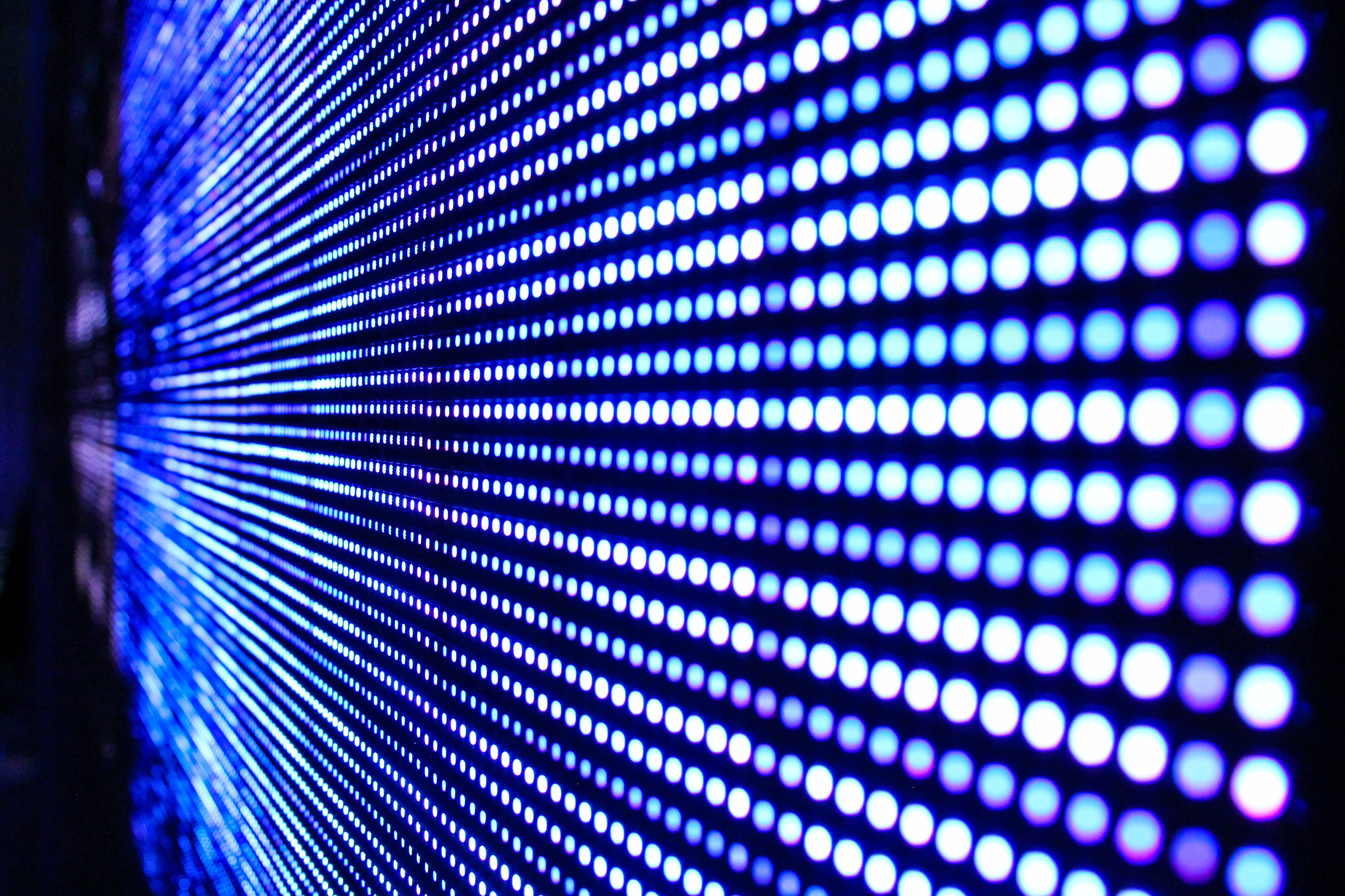
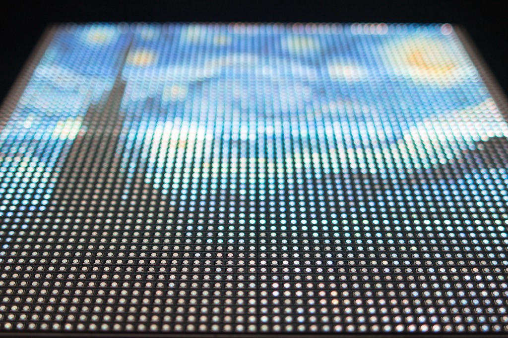
Meeting the HUB75 LED Panels
I started to make a small video game console with my son during Summer 2016 and while searching for pieces of hardware (especially LCD screen) I stumbled across this piece of hardware at Adafruit:
It was a board capable of addressing and driving HUB75 LED panels.
I was impressed by the possibilities of such panels and how interesting and useful it could be.
What I had in mind at that time was:
-
first, for our office, we could have various important information displayed on these large and comfortable panels. Server status, sensor values, beacon information, even time. The simple and impactful display would have been useful for the whole team. Nothing is better than a big and understandable signal on the wall, right? Think about Batman and his bat signal if you’re not convinced yet
-
Second, there were a few useful usages we could also make for our beacon project. As the Raspberry Pi 3 had a Bluetooth 5 chip it could be used as a BLE (Bluetooth Low Energy) beacon as well. So we could use the Raspberry Pi embedded Bluetooth chip as a beacon and display its information on the LED panels. To be more precise, the use case I had in mind was: as soon as some employee was nearing the vicinity of our office, we could have displayed his name and the name of all people present in our office (our office were not that big at the time).
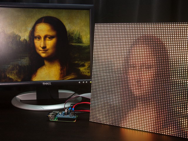
So I ordered one and started playing with it.
It worked immediately following instructions on Adafruit web site.
Well, it worked as expected but it was not as flexible as I possibly imagined. At least for the usage I had in mind and talked about previously. It was only possible to have one or two led panels and not much. Not big enough for my purpose.
So I dived a bit deeper.
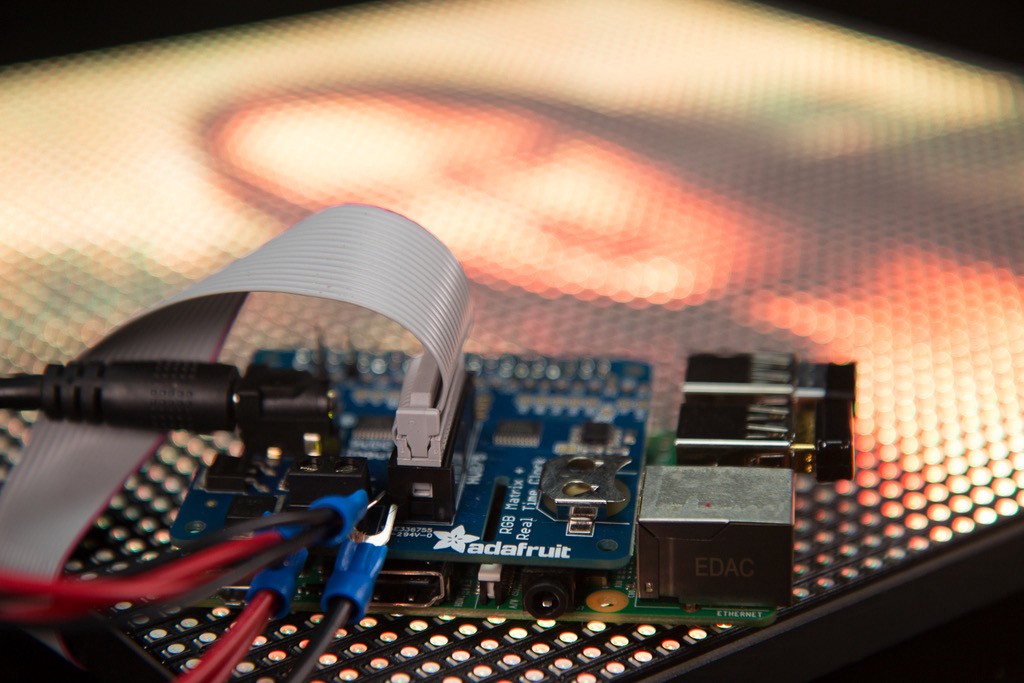
The board Adafruit came up with was something as ‘simple’ as
-
power management with protection
-
two 74HTC245 chips to address and drive PWM for a single chain of led panels.
-
Level shifters to ensure proper levels and thus avoid glitch while driving the led matrix
-
A Real-Time Clock to allow the display of a precise clock on the panel
With the two octal bus transceivers and single connector for the panels, it made a recommended maximum size of 64x128 pixels.
I also noticed that the software used to drive the matrix forked the work of Henner Zeller (more documentation is available in the library author’s repository) and immediately tried to use it instead of Adafruit’s fork and it worked as well. But something attracted my attention. Henner Zeller was talking about hardware in greater details and was recommending a homemade PCB to drive the matrix panels offering much more space with 3 separate channels.
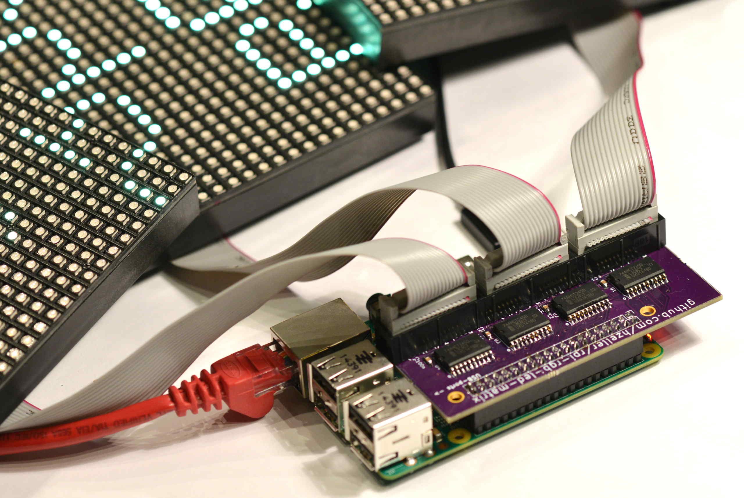
Wow, exactly what I wanted. So I decided to give it a try and ordered the PCB from OSH Park and all components. A few weeks later I was ready to solder these surface mount components (SMD) together with my co-worker Jérôme Stienne and we did it successfully even though we never had soldered SMDs before (I used a technique similar to this one). I must say though that we had some solder bridges that occurred beneath some of the components preventing the board to work as expected and Jerôme patiently debugged it 👏.
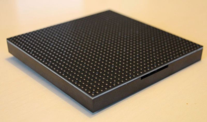
So that we had this three-channel matrix driver working and we were ready to build a big screen of pixels. It was time to order those LED panels and I ordered six of those. They had the smallest pitch (distance between LEDs) and gave us the possibility to draw something with a reasonably good image definition even at close range.
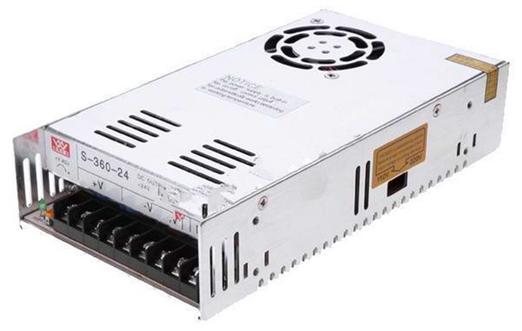
I also had to find something able to power it and went into the maths: to calculate the power, multiply the width of all the chained matrices * 0.12 Amps : a 32 pixel wide matrix can end up drawing 32*0.12 = 3.85A so around 4A for a 32x32 panels and I had six panels of twice that size which made 48A! You can easily find this kind of power on Amazon. They are bulky, heavy but they do the job :)
And finally we had to assemble all these panels and this was not so simple.
Assembling the final hardware
The panels I had was 32x64 LEDs assembled on a large PCB on which a plastic frame was screwed. On those plastic frames, you could screw small magnet pads delivered with panels. It is convenient if you want to ‘stick’ your LED panel on a whiteboard but the magnets were not strong enough to maintain the whole 6 panels together. We had to find a better way and Henner Zeller came to the rescue once again. In one of these proficient readme-files, he explained how he powered every panel and added a useful picture of his own panel assembly.
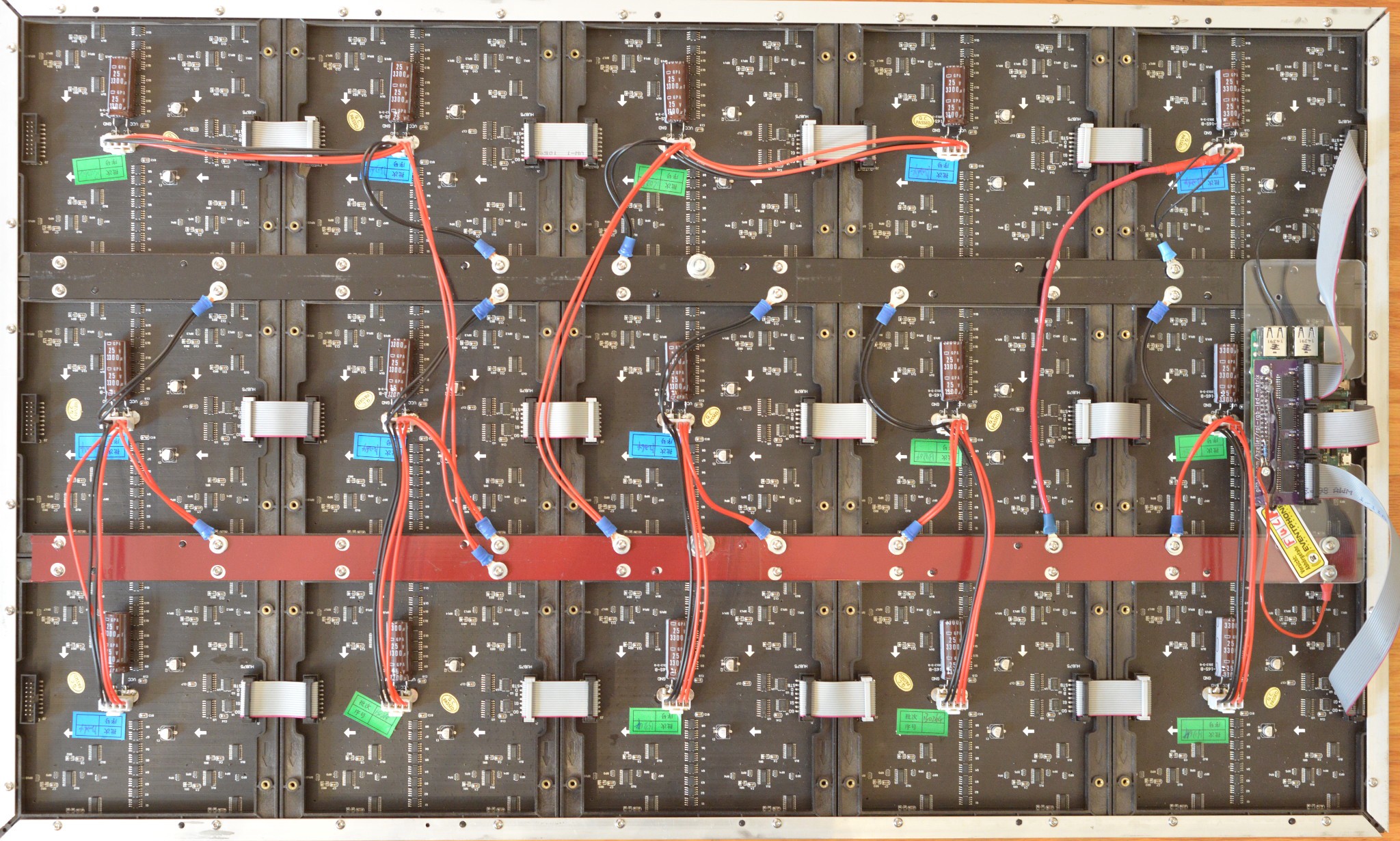
He used aluminium corners and used the screw holes of the panels to build a frame on which the panels were maintained together and used two aluminium bars to propagate power along with the panels.
So we went this way and finally had our big panel ready!
Now we are ready for part 2: the software! Making a graphics driver for a led panel